Thursday, 2 August 2018

What is RSTP and PVST?

RSTP:-Stand for Rapid Spanning Protocol. Is defined in 802.1w.

That is used to prevent STP loops and also reduce the conversion time of STP.
We know that by default STP takes 30 sec. to 50 for blocking state to forwarding state. but when we configure RSTP, RSTP takes 10 sec. for coming forwarding state.


How to Configure RSTP?

Switch(config)#spanning-tree mode pvst


PVST:- Stand for Per-VLAN Spanning Protocol. Every VLAN has a Separate STP run that is known as PVST.


Wednesday, 1 August 2018

What is STP( Spannig Tree Protocol) and how does the spanning tree protocol (STP) work?

Hello, friends welcome to my blog tutorials my name is Dinesh Kumar Gupta in the last tutorials we discuss inter-VLAN.

           now today I will discuss that What is Spanning Tree Protocol? STP terms?
So let's understand...


What is Spanning Tree Protocol?

STP:- Stand for Spanning Tree Protocol that provides the loop-free network when you have multiple links between the switch and also provides redundancy.
It is an Open Standard Protocol (IEEE 802.1D)
STP stop the broadcast Strome, multiple frames copies & database instability.
By default, STP runs all Cisco Catalyst Switch.


STP Terms

(1) Root Bridge
(2) Root Port
(3) Blocking Port
(4) Forwarding Port
(5) Designated Port


How STP works


(1) Root Bridge:- First of all selecting the one  Root Bridge into all switches witch the help of priority value (by default priority value of every switch 32768+1 (vlan 1 ) =32769) and MAC address

Bridge ID = least of priority value+MAC address.

out of all the switches in the network one is elected as a Root bridge that became the focal point in the network switches and all the frame transfer one point to another point.
One is Root Bridge and all Non-Root bridge.


we can see the bridge ID of every switch

Show command is
Switch#show spanning-tree


(2) Root Port:-After selecting the Root Bridge now selecting the Root Port the Root Port shortest path Every Non-Root Bridge looks the best way to go Root Bridge.

but how to finds the best way? just Three measurements. 

    (a) Lest Cost (Speed)
    (b) The lowest Forwarding Switch ID
    (c) Lowest Physical port Number


STP Port Cost

Link Bandwidth          STP Cost

4  Mbps                           250
10 Mbps                          100
16 Mbps                          62
45 Mbps                          39
100 Mbps                        19
155 Mbps                        14
622 Mbps                        6
1  Gbps                           4
10 Gbps                          2


(3) Blocking Port:- That port that is used to disabled the loops.

   There are two of Port in a Network
   (a) Forwarding Port:- Forwarding Port always enable. this port never is disabled.
        in this data send and received.
   (b) Blocking Port:- Non-Forwarding that means in this port can't forward the data.

STP Port State

 Port                    time

Blocking            20 sec. or no limits
Listening           15 sec.
Learning            15 sec.
Forwarding        no limit
Disable               no limit

What is Portfast?

Portfast is a feature of Cisco Devices that are used to disable STP and it is used to reduce the conversion time. when we connect the end user device the conversion time reduce.
but if we connect to layer 2 devices with this port fast it can create loops.


Configuration Command is

Switch(config)#interface fastethernet 0/1
Switch(config)#spanning-tree portfast

We Can Change the Root Bridge to the following command
there are two methods we can change the Root bridge


(1) Switch(config)#spanning-tree vlan 1 root primary
(2) Switch(config)#spanning-tree vlan 1 priority 4096


What is BPDU Guard?

BPDU:- Stand for Bridge Protocol Data Unit
If we configure port fast and after that the connecting layer 2 devices it can create loops but at this time we use BPDU Guard.

Configuration command is

Switch(config)#interface f0/2
Switch(config-if)#spanning-tree bpduguard enable
Switch(config-if)#exit


That for reading my tutorials...


Tuesday, 24 July 2018

What is Inter VLAN Routing and Router-on-stick? and configuration.

Hello...guyz..! welcome back my tutorials friends today I will discuss Inter VLAN Routing and Router-On-stick.

let's understand that what do u means these Routing.

Inter VLAN Routing:- A method that is used to communicate different  VLAN of the subnet.
In this method, we use a layer 3 device. Such as Roter.
Once a host is separated through the VLAN, member host of the same VLAN can communication
with each other.


Configuration Inter VLAN Routing,


first of all, go to the router and command is


Router>enable
Router#configure terminal
Router(config)#interface f0/0
Router(config-if)#ip address 10.0.0.1 255.0.0.0
Router(config-if)#no shutdown
Router(config-if)#exit
Router(config)#interface f0/1
Router(config-if)#ip address 20.0.0.1 255.0.0.0
Router(config-if)#no shutdown
Router(config-if)#exit


after that go to switch here command is 


Switch(config)#vlan 10
Switch(config-vlan)#vlan 20
Switch(config-vlan)#exit
Switch(config)#interface range fastEthernet 0/1-2
Switch(config-if-range)#switchport access vlan 10
Switch(config-if-range)#exit
Switch(config)#interface fastEthernet 0/6
Switch(config-if)#switchport access vlan 10
Switch(config-if)#exit
Switch(config)#interface range fastEthernet 0/3-4
Switch(config-if-range)#switchport access vlan 20
Switch(config-if-range)#exit
Switch(config)#interface fastEthernet 0/5
Switch(config-if)#switchport access vlan 20

 Switch(config-if)#exit


Router-on-stick:- It is the second method is if we want to communicate different VLAN of the subnet here is also required layer 3 device such as Router.

The process of connecting one physical link with the trunked logical(sub) interface is known as Router-on-stick.


Configuration of Router-on-stick 


the command is

go to on router

(config-if)#no shutdown
Router(go to on router

Router>enable
Router#configure termianl
Router(config)#interface f0/0
Routerconfig-if)#exit
Router(config)#interface f0/0.10
Router(config-subif)#encapsulation dot1Q 10
Router(config-subif)#ip address 10.0.0.1 255.0.0.0
Router(config-subif)#no shutdown
 Router(config-subif)#exit
Router(config)#interface f0/0.20
Router(config-subif)#encapsulation dot1Q 20
Router(config-subif)#ip address 20.0.0.1 255.0.0.0
Router(config-subif)#no shutdown
Router(config-subif)#exit


after that go switch


Switch>enable
Switch#configure termianl
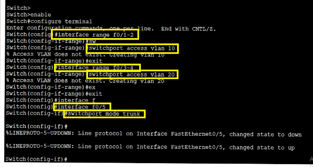
Switch(config)#interface range f0/1-2
Switch(config-if-range)#switchport access vlan 10
Switch(config-if-range)#exit
 Switch(config)#interface range f0/3-4
Switch(config-if-range)#switchport access vlan 20
Switch(config-if-range)#exit
Switch(config)#interface f0/5
 Switch(config-if)#switchport mode trunk


Sunday, 22 July 2018

What is DTP?Switch Port Mode?

Hello..., Guyzz my name is Dinesh Kumar Gupta. today I will discuss that What is DTP? and Switch port mode.

What is DTP?

DTP:- stands for Dynamic Trunking Protocol.it is a Cisco proprietary protocol. In this protocol, that is used to automatically negotiates the Trunking protocol between Switch. that means automatic assign Switch port in access port or Trunk Port.here is working protocol the protocol is ISL (Inter-Switch Line ) and 802.1Q.it uses 30 seconds to transfer the message to each other.


Switch Port Mode


(1) Administrative Mode

 Administrative also called is input mode.

(a) Access mode
(b) Trunk Mode
(c) Dynamic Desirable
(d) Dynamic Auto
(e) No negotiate


(2) Operational Mode

     Operational Mode also called is output mode.

(a) Access Mode
(b) Trunk Mode


What is VTP? VTP Mode and Configuration?

Hello, friends, my name is Dinesh Kumar Gupta in this tutorial we understand that  What is VTP?VTP Mode and Configuration. 

 Let's start now....!  


VTP: Stands for VLAN Trunking Protocol. It is used to transfer the VLAN database dynamically one Switch to another Switch. by using the trunking protocol. 


There are three VTP Mode 


(a) Server Mode:- In this mode, all information from the VTP server Switch will be synchronized to the VTP Client Switches. by default, all the Cisco switches will be in the Server mode even when there multiple VTP Server. VTP Server can create VLAN, do modify as well can delete the VLAN


(b) Client Mode:- In this mode only see the VTP status and receives the information from the VPT server if the client VTP wants to create VLAN don't create the VLAN.


(c) Transparent Mode:- In this Mode Switches do not participate in the VTP Domain. can add and create VLANs


The requirement of configuration VTP


(1) Change the Hostname 
(2) Configure Trunk Port 
(3) Configure VTP Domain 
(4) Configure VTP mode

Command is

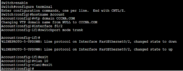
Switch>enable
Switch#configure terminal
Switch(config)#hostname Account
Account(config)#vtp domain CCCNA.COM
Account(config)#interface f0/2
Account(config-if)#switchport mode trunk
Account(config-if)#exit
Account(config)vlan 10


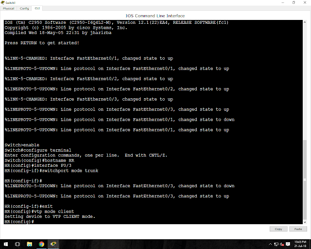
Switch>enable
Switch#configure terminal
Switch(config)#hostname HR
HR(config)#interface F0/3
HR(config-if)#switchport mode trunk
HR(config-if)#exit
HR(config)vtp mode client


Switch>enable
Switch#configure terminal
Switch(config)#hostname SALES
Switch(config)#vtp mode transparent


Show VTP mode
Command is
switch#show vtp status


Saturday, 21 July 2018

What is TCP/IP model?

Hello... friends, my name is Dinesh Kumar Gupta.
friends in this tutorial we discuss the TCP/IP model


TCP/IP

Stands for Transmission Control Protocol and Internet Protocol in
this model that define a set of rules to govern communication among all device connected to the internet. TCP Transport is often used to transfer data across IP networks.
It is also called/knows as Internet Protocol Suite.


Comparing the TCP/IP suite with OSI layers


The TCP/IP reference model, also know as the DARA Defence Advanced Research Project Agency )
model after the U.S. government agency that initially developed it consists of Four layers as opposed to seven-layer Open system interconnection (OSI).


The four layers of the TCP/IP reference model are 


1. Application Layer
2. Transport Layer/Host-to-Host layer
3. Internet Layer
4. Network access layer/Network Interface Layer


1. Application Layer:- In this layer define the protocol that application use data transfer while many new application that is currently used in:

such as HTTP, HTTPS, Telnet, DNS, DHCP, RDP, FTP, TFTP, SNMP, NTP, SMTP, POP, IMAP, etc


2. Transport Layer:- In this layer responsible for end-to-end communication to ensuring that all the packet arrive in sequence and also with an error.

Here it Works two Protocol.

(a) TCP(b) UDP


Different between TCP and UDP

TCP:-

Stands for Transmission Control Protocol
TCP uses Port No. 6
It is reliable.
It provides guaranteed data.
It is a connection-oriented protocol
It is used for hight amount of data transmission.
and TCP slow as compared to UDP.


TCP  uses three handshake messages SYN-SYN+ACK-ACK


UDP:-

stands for User Datagram Protocol
UDP uses Port No. 17
It doesn't provide guaranteed of data.
It is a connection-less protocol.
it uses the small amount of data transmission
and UDP fast as compared to TCP.  because of UDP packet transfer in broadcast 


Internet Layer:- In this layer similar to the Network layer of the OSI model and also responsible for accepting, routing and delivering data packets.


the core protocol of the internet layer include Internet Protocol (IP), Address Resolution Protocol (ARP) Internet Control Message Protocol (ICMP Revert Address Resolution Protocol (RARP),  and Internet Group Management Protocol (IGMP)

ARP:- Address Resolution Protocol that is used to resolve IP address into MAC Address

RARP:- Revert Address Resolution Protocol that is used to resolve MAC Address into IP Address.

ICMP:- Internet Control Message Protocol that is used check the connection.

IGMP:- Internet Group Management Protocol that used to the multicast purpose.


Network Layer:- In this layer use to access the Network service and uses some LAN Technology as well as use Transmission media 

ex: Ethernet, Token Ring, FDDI, X.25
      Coaxial Cable, TP, Fiber Optics cable. 


Thursday, 19 July 2018

What is OSI Model? Seven layer of the OSI model?

Hello..guyzz..! welcome back my blogger my name is Dinesh Kumar Gupta.
    Friends...today I will discuss What is OSI Model? and Describe 7 effective Layer of the OSI Model as well as understand PDU (Protocol Data Unit) of the OSI Model.


 So let's start now, first of all 


What is OSI Model?

OSI Stands for Open System Interconnection. It was published in 1984.
OSI model was first proposed by International Standard Organization (ISO) to solve the multiple problems faced in Telecommunication it is a conceptual model of telecommunication networking where the whole process is divided into seven effective layers. 


SEVEN LAYER OF THE OSI MODEL

(1) Application Layer
(2) Presentation Layer
(3) Session Layer
(4) Transport Layer
(5) Network Layer
(6) Data-Link Layer
(7) Physical Layer 

And According to formate of the OSI Model

(1) Physical Layer
(2) Data-Link Layer
(3) Network Layer
(4) Transport Layer
(5) Session Layer
(6) Presentation Layer
(7) Application Layer


Let's understand every layer of the OSI Model


 (1) Physical Layer:- This layer is the primary layer of the OSI Model and consists of connecting device such as Ethernet cable, Token ring, hubs,                                            repeaters. this layer responsible for connecting the device to physical transmission media such as copper or optical or  Radiofrequency and also called the hardware layer or lower layer.


(2) Data-Link Layer:- in this layer encode and decode data packet into bits and using its transmission protocol. it handles the error in the physical layer. it also controls flow and synchronization of the frame and at the same time, it manages controlling access to the physical layer network device.


(3) Network Layer:- In this layer adds the concept of routing above the data link layer. When data arrives at the network layer, the source and destination address contained inside each frame are examined to determine if the data has reached its final destination. if the data has reached the final destination, this layer 3 formats the data into packet delivered up to the Transport layer.


(4) Transport Layer:- In the fourth layer, the variable length data sequence has to be transferred from source to destination host through one to more network. this Transport layer delivers data across the network connection.The supported protocol at this layer are TCP (Transmission Control Protocol) and UDP (User Datagram Protocol)


(5) Sessions Layer:- In this layer responsible communication or connection between the computer and establishing connections between local and remote applications.


(6) Presentation Layer:- In this layer here is a simple function of any pieces of the OSI model. here is handled syntax processing of the message data such as formate of data, encryption/decryption. 


(7) Application Layer:- In the last layer of the OSI model this layer represents the data is understood by the end user.the application layer supplies network services to the end-user application. network services are typically a protocol that works with user's data.
for example, in a web browser application, the application layer protocol "HTTP" (Hyper Text Transfer Protocol ) is also called a software layer or upper layer.


PDU in OSI Model:-


(1) Application Layer:- DATA ( the data received or transmitted by a software                                                                  application )
(2) Presentation Layer: -DATA ( Formatted of data )
(3) Session Layer:- DATA  ( The data passed to the network connection )
(4) Transport Layer:- SEGMENT (A segment that includes a TCP header and                                                                      data)
(5) Network Layer:- PACKET  ( contain the source and destination address)
(6) Data-Link Layer:- FRAME ( Series of bits )
(7) Physical Layer:- BITS  ( 0, 1 )


What is RSTP and PVST?

RSTP :- Stand for Rapid Spanning Protocol. Is defined in 802.1w. That is used to prevent STP loops and also reduce the conversion time o...